
How to: Build a replica Cannon Part Three
- Tastes Of History
- Nov 25, 2020
- 6 min read
Updated: Nov 8, 2025

The Gun Carriage
In Part Two we looked at seven steps to building a barrel for a replica naval gun that was both lightweight and portable. The completed barrel needed a gun carriage, however. So, starting at Step Eight, in this Part we will explore one way to make a simple gun carriage to support the barrel.

Step Eight Once again, the result had to be lightweight and robust, not only to support the barrel but to survive the rigours of transportation and manhandling. As shown below, the stepped shape of each “bracket” was built from hardboard supported by wooden noggins, all of which was glued and screwed together. Small counter-sunk brass screws were favoured so that, with filler, they can be suitably disguised.

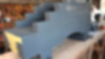
One concession to ensuring robustness was to insert a hardboard panel (not shown above left) attached to the cross-ribs between the brackets. Five and a half millimetre thick plywood strips (above right) were pinned in place to conceal the noggins. When combined with multi-purpose filler to disguise any gaps, the illusion of solid wood can be created. The addition of shallow, longitudinal grooves, cut with a tenon saw and filed to shape, further give the impression that the brackets are constructed from several pieces of solid timber (see above).
Step Nine Without a lathe to turn four “trucks” (wheels), each one was made by gluing three 18 mm plywood discs together (overall width 54 mm). The discs themselves can be cut with a jigsaw or using a router, the latter being the option chosen in this case. The original plan intended each truck (wheel) to have a diameter (Ø) of 190 mm. With the gun carriage built, this seemed slightly out of proportion, so the diameter was increased to 270 mm for both the front and rear trucks.
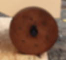
The liberal application of wood filler round the circumference of each truck, sanded smooth, and then each one stained a mahogany colour, created the look of solid wooden wheels. The trucks on most examples of original gun carriages also seem to be made of more than one disc of material. Where two or more discs are used, then these are usually bolted together. Six clout nails were therefore hammered into each of the four trucks to represent these bolts. One of the four completed trucks (wheels) is shown right.
The fore and hind axletrees on a gun carriage were typically made from square section timber radiused at either end to fit the centre holes of the trucks. To lighten our design, however, we chose to construct two plywood boxes (410 x 130 x 125 mm) with internal brackets to support each of the two 40 mm Ø axles (as shown below). Two additional boards (not shown above) were glued on each side to enclose the axle and make the axletree appear to be solid wood. The axletrees were attached to the underside of the carriage by wood screws.
A 5 mm Ø hole was drilled in the centreline of each axle approximately 10 mm from each end to receive an axle pin. Each pin was made from a repurposed 4 mm Ø round wire nail set in a oval-shaped wooden block painted black to look like iron. These pins, which can be seen in the image of the completed truck above right, are removable so that the trucks themselves can be removed for transportation, if desired.

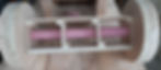
Step Ten With the basic construction completed, the whole gun carriage was primed and then painted. We chose to imitate the orangey-yellow paint scheme used aboard HMS Victory, Flagship of the First Sea Lord, which can be visited in Portsmouth Historic Dockyard. Matching the precise colour was a challenge, however. In the end, rather than having a bespoke paint mixed, we opted to use three tester pots of “Granada” matt emulsion [1]. The result after three coats is shown above.
The Ironwork
Step Eleven The next task is to recreate the ironwork for the gun carriage, such as the rings for the rope tackle [2]. Shaped brackets for the barrel trunnions, known as 'capsquares', needed to be fabricated, as did large faux bolts to replicate those that would have held the carriage together.
Capsquares The barrel trunnions are held in place on the gun carriage by two arched iron capsquares. One end of each capsquare is fastened over an iron wedge known as a capsquare fore-lock and held in place by a capsquare key passing through the wedge. At the other end, each capsquare is hinged about a capsquare eyebolt so that, with the key removed, the capsquare can be lifted up and rotated to release the trunnion. In this way the cannon barrel can be removed from the carriage.

The two capsquares were cut to create the arched shape from blocks of wood measuring 260 mm long x 50 mm wide x 50 mm high. The radius of the arch is 35 mm, and the resulting capsquare is 10 mm thick.
The u-shaped capsquare eyebolts were cut from 12 mm plywood, sanded to a round profile and glued onto each gun carriage bracket. The ends of the eyebolts were cut to form 'pins' used to locate them in pre-drilled holes to the rear of each trunnion.
The capsquare keys and fore-locks were cut from 5.5 mm plywood. The flange on each fore-lock allowed it to be glued into a slot cut to receive it located forward of the trunnion on each gun carriage bracket. A metal chain was connected to each key through a 5 mm Ø hole. Using a threaded eyebolt, the chain and key were fixed to the gun carriage brackets just below the capsquare fore-locks. Each piece of the capsquare assembly was primed and painted black to look like iron.

Bolt heads Large nylon cover buttons, spray painted black, were glued in the appropriate position to replicate the bolts that pass through the carriage and hold it together. Smaller diameter buttons were used to replicate the bolts securing the axletrees.
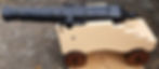
Gun tackle ring bolts Missing from the image above are the ring bolts used to attached the ropes and pulleys of the gun tackle used to haul cannon inboard for loading and outboard for firing (see Part Six). These rings are shown in the image below of one of HMS Victory's guns.

The simplest solution, we thought, was to purchase suitably sized iron ring door pulls from an ironmongery or hardware supplier. Finding ring pulls of the correct scale proved surprisingly difficult, so the decision was made to fabricate them in much the same way as we had for the other “metalwork”. Firstly we sourced a set of wooden curtain rings that seemed to be of the right scale. The next challenge was how to attached them to the gun carriage. The iron rings fitted to the cannon aboard HMS Victory were clearly forged in a single piece with, it seems, an integral spike for hammering the ring into the woodwork of gun carriage as shown above. As we used wooden rings this was not an option, and to complicate matters our gun carriage was a box construction and not of solid timber. The solution was to fabricate u-shaped wooden blocks to clamp the gun tackle rings in position. While for the breeching line rings, we copied the basic design of the Capsquare Fore-lock, albeit slightly shortened and with the slot replaced by a single hole. Both mounts were made from 20 mm thick wooden blocks which were pinned and glued in place.

The resulting rings and mounts were painted black to look like iron.
Next... With the barrel and carriage complete, the gun will needed something to “fire”. So, in Part Four we will explore “How to:” recreate some of the different projectiles used in the Age of Sail.
Endnotes:
1. The tester pots were purchased from the “GoodHome” range at B&Q. Other DIY or paint retail outlets may offer the same or even a more accurate colour. ▲
2. The description of a typical gun's rigging was retrieved from the website Model Ship World. ▲